The service life of the component machine / hoist
Quaderni ANICA – Stefano Bertoni, Lorenzo Calvi, Antonio Imbimbo & Antonio Lizza
Slow Shaft
Modern machines are essentially isostatic, i.e. with a slow shaft on two bearing brackets. In the past, there was a tendency to favour the hyperstatic configuration with a shaft on three bearing brackets, essentially due to the widespread use of bronze bushings rather than modern bearings. Lubricated for life bearings are the preferred choice as they are sealed to prevent contamination and deterioration resulting from external materials or lubricants.
Shaft materials and finishes are of the highest quality, given the importance of this component. Particular attention is paid to the variable profile of the cross-sections, which is gradual, in order to avoid critical cross-sections where the effects of notching, together with fatigue loading, can lead to problems over time.

Length of cross-section variation (in the green circle) and support points (indicated by the green triangles).
EN 81-20 and 50 require the transmission of torque through positive mechanical means, which is why there are keys with the relative keyways on both the sheave side and the coupling side of the crown wheel/slow shaft. These profiles represent natural loading accumulation points and, although they have isostatic shafts, operations performed during the service life of the winch (such as the replacement of the traction sheave, if not done according to the manufacturer’s specifications) can pose a problem affecting the service life and functionality of the component.
A typical example is the coupling with the front flange between the slow shaft and sheave, where the correct taper of the flange plays a fundamental role.

Sheave/slow shaft coupling flange.
Incorrect fastening, whether due to problems with assembly or an incorrect taper, can lead to decoupling of the parts over time. Under impulsive loads, such as those during the testing of safety components, and also during simple work cycles, high levels of stress concentration in the keyway could therefore occur, with the possibility of immediate damage to the cast iron sheave (e.g. during the parachute test) or with typical fatigue damage on the steel shafts, which is extremely harmful as it occurs slowly over time, is silent and often concealed from view.
The crack begins at the keyway and spreads along the length of the shaft in the form of a rupture until cleavage fracture, which affects the small section still in operation, occurs.

Typical development of a fatigue fracture in shafts: note the section where the final fracture occurs (in green).
If suitable tools are not used, the replacement of bearings can also cause localised damage to the shaft. This can cause cracks to develop which then lead to fatigue failure. If the shaft is damaged, under no circumstances should any attempt to repair the damage, e.g. by welding. This will cause an alteration of the mechanical characteristics, locally, and will be the cause of a failure. A damaged shaft must be replaced.
Hyperstatic shafts are still possible, for example, if the sheave is located at a greater distance from the body of the machine (long slow shaft), however in this case it is not possible to fit an emergency brake (device against uncontrolled movements or UCM) on the shaft. Particular attention must be paid to the perfect alignment of the shaft during the installation of this type of configuration.
These configurations are often typical of hoists positioned at the bottom or to the side of the compartment. In order to avoid any misalignment, it is also essential to implement suitably rigid and adjustable “recessed” frames, which fully absorb the deformations induced by the “cantilever” configuration.
Diagram of a recessed frame for a hyperstatic shaft. Note the high level of rigidity of the frame, the adjustments, the vibration dampers and the attachment of the intermediate shaft support, made below the upper section of the frame.
Worm gears
The worm gear forms the coupling between the slow shaft and the drive shaft, resulting from the interposition of the crown wheel. The screw itself is not subject to significant rotary fatigue loading, as it compact and confined between the bearings. The proper design of the profile of the screw, guards against the effects of notching.

Worm gears: note the pattern of normal and lateral forces, resulting from contact with the teeth of the crown wheel.
Lubrication is the most important aspect for the proper functioning of the worm gear/crown wheel coupling and for safeguarding the integrity of the component parts.
Modern synthetic lubricants with the correct additives for use with high pressures are used, also paying careful attention to the surface finish of the parts. In an ideal condition, the roughness of the parts is such that there is no actual contact, allowing a uniform lubricant gap under pressure, protecting the metals of different characteristics from the wear that they would cause on one another. An adequate lubricant gap, obviously, reduces friction significantly.
A critical condition of the lubricant due to degradation, the incorrect choice of lubricant or the presence of materials resulting from component wear, can result in failure, as shown in the diagram below.
The onset of localised friction resulting from lubrication problems creates local rises in temperature which can lead to strain hardening of the steel in the elements. The resulting change in mechanical characteristics leads to damage.
Of equal importance is the acidity of the lubricant (which increases as the lubricant degrades), the effects of which lead to the chemical corrosion of the components. Regardless of the correct viscosity or a simple change of lubricant, this can create problems.
Cast-iron housings
At present, the preferred method is for cast iron housings of gear motors to be manufactured as a single component. This allows for stronger, more compact components that take advantage of the particularly suitable behaviour of cast iron to withstand compressive loads and the more efficient transfer of loads to the frame below.
The correct “functioning” of the structural part of a motor only occurs if the interaction between chassis and machine is correct. Of particular importance is the choice of material and the size of the buffers and anti-vibration elements. This aspect is also important for gearless motors, particularly in the MRL configuration, in compartments where particular criticalities may occur. In particular, given their proximity, the vibration dampers close to the traction sheave are subjected to much more significant stresses than their more distant counterparts.
Similar phenomena are inherently dangerous (the motor practically rests on one side only) and cause tilting which makes the ropes work on the sides of the grooves. This negatively affects gripping action due to abnormal wear on the sides of the groove. The placement of a plate in the direction of the sheave, along with extended anti-vibration material, protects against wear from occurring.
Brakes
UNI 10411-1:2021 has also focused attention on the machine brakes. Current regulatory standards require that the mechanical parts which perform the braking action are independent from one another, and that each of them is capable of effectively braking the full load on its own. The solenoid, on the other hand, may be shared. It is not always easy to distinguish the actual mechanical independence of the braking elements. In fact, despite having two separate braking elements, some brakes function in such a way that a single failure can inhibit the operation of the entire unit.
Empirically, but not in a precisely exact manner, seeing a single axial element that connects the two clamping jaws on which the springs are housed often results in a dependency of the elements.
Management of gearless motors
An operation of particular importance for the correct and smooth operation of a gearless motor is the initial timing. Generally, this procedure is automatic and is performed by the inverter and consists of aligning the electric fields of the stator and rotor. An inverter will only phase correctly if it is properly configured through fine tuning. Performing several successive tuning procedures is important in order to verify that the same result is achieved in terms of the angle of the encoder. This will ensure the highest constant torque possible and reduced currents. A further test to be carried out before loading the sheave is to rotate the machine in both directions and check that it has the same voltage and very low currents, in the order of 0.3 / 0.5 A. Once the system has been tensioned, the maximum current measured is then checked to ensure it is consistent with that indicated on the nameplate.
These precautions will allow the motor to operate within the optimal voltage range, avoiding over-modulation on the part of the inverter, an indication of vibration. Similarly, correct regulation, and therefore regular current draw within the ratings, will prevent the excess current that the motor is unable to transform into torque and will generate heat, resulting in progressive deterioration of the motor.
The main parameters to be taken into account when it is necessary to perform fine tuning for which we cannot leave the default parameters of the inverter, are the proportional gain of the current loop (the amplitude with which the adjustment is carried out) and the current loop integration time (speed of integration). Similarly, the speed loop can be adjusted, bearing in mind that the speed gains change depending on the operating speed, essentially by setting the appropriate “transition” frequencies.
“Backlash” between the teeth in lift hoists
“Backlash” refers to the gap between the teeth of the worm gear and the crown wheel. This is essential for transmitting motion in the correct lubrication conditions. This gap is destined to increase over the course of the useful service life of the machine, as a result of inevitable wear and tear; The proper design of the drive will ensure the minimum backlash required for operation, while at the same time trying to ensure greater durability.

Illustration of “backlash” between the worm/crown.
In this sense, determination of the correct lubrication gap ensures against overheating which, as is well known, leads to expansion in the metal components, with a consequent reduction in the amount of “backlash” itself, thereby resulting in cascading failure.
Correct sizing of the backlash requires the temperature to be taken into account, as per the following formula that defines the value for the backlash.
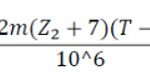
Relationship between temperature and backlash. m = axial modulus; 𝑍2= number of teeth; T = temperature
It is therefore clear that the correct value for backlash does not depend on the specific machine and its reduction ratio.
The thickness of the tooth gradually decreases and must not become so thin that safety is compromised. In the case of lifts, backlash is usually noticeable and becomes annoying long before the conditions are reached. Example of cabin bounce when entering and exiting, or bounce when changing speed during deceleration at floor level.
A widely used limit condition is that the maximum backlash must not exceed: 0.3 m with axial module m.
Although the machines are constructed and tested in such a way as to guarantee their perfect operation from the time of commissioning, there is a typical run-in phase during which there is a rapid increase in “backlash” in the first phase, which will develop much more slowly once the run-in has been completed. Generally, the run-in phase lasts between 200 and 600 hours.
Backlash can be assessed on the installation on site by blocking the slow shaft, turning the worm gear and measuring the angle of rotation, or measuring the arc of a circle over a known diameter. To block the slow shaft without having to lift the ropes from the traction sheave, simply rest the counterweight on the buffers with the cabin empty.
However, care must be taken to ensure that there is no axial movement of the worm gear or that any movement is minor and therefore negligible (hundredths of a millimetre) as this would add to the backlash and provide a false measurement.
While the measurement of the minimum backlash value is of little importance as the machines are delivered having already been tested, backlash depends on the individual machine and reduction ratio, and is therefore not a universal value; however the maximum values are certainly of greater interest.
Each manufacturer specifies a method and the maximum permissible play for its hoists, however, considering that the maximum amount of backlash must not exceed 0.3 m, it follows that the arc formed with this value is approximately 35°, which added to the initial backlash can increase by approximately 2°-3°.
It is advisable not to achieve this maximum value as the machine would then have to be stopped, but rather backlash should be limited to 1/16 of 360° (about 22°), allowing plenty of warning time before any real danger occurs.
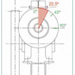
Angle of rotation “when empty”. This should not be exceeded.
Wearing of the grooves
Wear of the grooves is caused by multiple, complex factors which are interconnected and develop, inevitably, over time through the physical interaction of parts that are inextricably linked by their relative movements.
It is well documented that the main cause of wear is the specific pressure generated by the rope tension on the sheave groove, without taking into account assembly errors and the balancing of tension of the ropes; however, factors relating to different peripheral speeds of the ropes must be taken into consideration.
In fact, even though the ropes are secured to the same fittings (sling, counterweight), the simple fact that, either due to uneven necking or because of the different directions of the strands (resulting in diameters which are not precisely identical), this leads to the ropes travelling at different speeds, the thinner ones being closer to the axis of rotation than those with a larger diameter (of course, we are talking about tenths of a mm). With the same stroke, the outermost ropes will have travelled a greater distance than the innermost ones, performing a sliding movement to then find themselves all in the same position in relation to the fittings. It therefore follows that the increased wear on a rope because it has not been equally tensioned (as it differs slightly in diameter from the others), will result in cascading degradation that is bound to worsen rapidly. It is also for this reason that, where possible, the ropes should all have the same stranding direction, and belong to the same batch.
Looking once again at specific pressure, ever since EN 81-1:1998 and therefore also contained in the current EN81-20 and 50 standards, it is no longer taken into account because these standards emphasize safety and not performance, and wear from the sheave is not considered an actual hazard whereas rope wear and rope failure are considered to be hazards. It is, however, clearly a mistake not to consider the specific pressure in the grooves in order to also ensure a long service life for the traction, or rather friction, sheave.
Much has been written about this subject, and a correct assessment of the specific permissible pressure should take into account the speed and frequency of use, as shown in the graph below.
Analytically, this family of curves responds to the ratio: P≤ PD = (12.5 + 4 VC) / (1 + VC) x k (N/mm2)
With k = (52 –(z / 60)2 –z / 60) / 50 where z = start-ups/hour
A further parameter to be considered, in order to ensure a longer service life for the sheaves is selecting the correct hardness for the material which makes up the sheave, in relation to the material used for the outer strands of the ropes.
Wear assessment: U-shaped grooves
One of the values that can be measured to have an indication of the degree of wear in the grooves is rope penetration in the groove itself. Unfortunately, there is no unified value and such considerations may vary from one manufacturer to another. Generally speaking, it can be said that for 8 to 16 mm ropes for sheaves with semi-circular grooves and with notches, rope penetration in the groove, compared to the initial condition, must not exceed d/2-6 mm.
More generally still, the wear in a semi-circular groove with notch does not affect gripping action until the rope touches the bottom of the notch
However, uneven wear which leads to differences in depth of more than 1 to 1.5 mm between one rope and another indicates a serious problem that needs to be assessed as it is symptomatic of the phenomenon of relative slippage between ropes due to differences in speed.
Wear assessment: V-shaped grooves
When the V-grooves begin to wear, they become semi-circular notched grooves where adhesion is no longer guaranteed by angle 𝛾 but rather by angle 𝛽. Given the greater complexity of the phenomenon of gripping action, more detailed considerations must be made.
“Relative consumption U/d” is defined as the ratio between the U penetration of the groove and its diameter; this will be linked to the geometric parameters of the angles involved, in accordance with the ratio.

Rope penetration also changes the actual angle 𝛽. “Specific wear of rope R” is defined as the following value:
It is not recommended to have specific wear R ≥ 8%.
As already specified for semi-circular grooves, wear must occur evenly across all of the grooves.
In the case of non-uniform wear, the safe state with regard to gripping action must be assessed by means of a test or by performing the calculation in consideration of the most worn groove.
Example 1:
V-groove with angle γ = 35° and specific wear of 8% corresponds to a semi-circular notched groove with angle β of 99°.
With a rope diameter, d = 10 mm, penetration depth U is 13.2 / 100 x 10 = 1.32 mm. Gripping action must therefore be checked once again as if the installation had semi-circular grooves at 99°.
Example 2:
On a sheave with a rope diameter of 10 mm and a γ angle of 38°, a wear depth of 1 mm was determined.
It is therefore calculated that U/d = 1/10 = 0.1 0 10%
From the table, the closest specific degree of wear to the obtained value is R=6. It then follows that the corresponding angle β is 101°.
Wear assessment: hardened grooves
EN81-1:1998 and, subsequently, EN81-20 and 50 specify that V-grooves without notches must be hardened in order to avoid premature wear as much as possible, and therefore reduce gripping action.
The hardening of cast-iron sheaves can increase surface hardness to values in excess of 50 HRC, which corresponds to a higher hardness than those of strands of the rope.
Wear in the grooves occurs in any case, therefore it is recommended to limit the specific pressure as per the formula.

Specific pressure with T = heavier side pull, n = number of ropes, d = rope diameter, D = sheave diameter, y = angle of the notch
It should be considered that, as soon as wear exceeds the hardening depth, there is a rapid degradation of the groove with subsequent deterioration of the gripping action. Given sp, the hardening depth (declared by the sheave manufacturer), it follows that:

Gripping action
The concept of grip is intricately connected to the phenomenon of groove wear. The traditional method of measurement to be carried out on site is described below.
Currently, EN 81-20 (SECT. 5.5.3) provides for the calculation of the gripping action with wide safety margins and includes a check (PAR. 6.3.3) during initial installation. The gripping action must be tested by performing several stops, in the severest of braking conditions, and the test must be performed with the cab empty in ascent and with 125% of the load in descent. No reference is made to the relative “permitted” value for slippage and the only requirement is that the complete stoppage of the cab must be achieved.
The only possible way to monitor the maintenance of the gripping action is to repeat the tests over time, taking note of the results in order to monitor any deviation of the initial result over time.
The first test consists simply of marking the ropes and sheave, performing a no-load ascent of the cab, followed by a cab descent with 125% of the load and then tracking any deviation of the marks on the ropes at the end of each run.

“Traditional” scheme for the slippage test.
There are two types of rope slippage on the traction sheave:
- One is due to the different tensioning of the ropes between the entrance and exit of the drive sheave and the pressure in the grooves which deforms the rope by stretching it.
- The other is slippage due to the lack of grip on the sheave: this type of slippage is dangerous if it occurs during normal lift operating conditions.
To assess the phenomenon, the concepts of:
- Long travel: this is the “roundtrip” distance of travel which occurs along the entire travel of the installation
- Short travel: this is the “roundtrip” distance of travel which occurs between neighbouring floors during which the installation is still able to achieve nominal speed.
The first type of slippage, defined as elastic, is such that the differences in slippage during acceleration and deceleration, in both long and short distance travel, will compensate for each other and the relative slippage encountered for both types of travel will be the same.
Where actual slippage occurs, the relative amount of slippage is not as significant during long travel as it is during short travel.
Therefore, a relative difference in slippage between short travel and long travel immediately indicates that a hazardous slippage zone has been introduced, as involves the problem of a lack of gripping action. In order to understand exactly what the predominant phenomenon is, it is necessary to compare the two results obtained from the long travel and the short travel during constant speed, deducing slippage as the result calculated by subtracting the slippage encountered during short travel from slippage encountered during long travel, since it is assumed that the acceleration and deceleration phases are the same.
Defined below:

The percentage of relative slippage is calculated according to the formulas shown below:
Short travel:

Long travel:

If 𝑆𝑠 ≥ 𝑆𝑐, there is actual slippage during acceleration and the situation is dangerous.
Example:

We have
Slippage during short travel:

Slippage during long travel:

It can be seen that, as a percentage, slippage during short travel is greater than slippage during long travel and, although the value is minimal with regard to the value for long travel, the method raises alarm as to the actual slippage which is occurring.
Notwithstanding the difficulties in performing the test, this methodology is also valid for gearless machines.
BIOGRAPHICAL DETAILS
Stefano Bertoni is an engineer, Technical Director of Montanari Giulio & C. Srl.
Lorenzo Calvi is an engineer, Technical Director of Alberto Sassi Spa.
Antonio Imbimbo is an engineer, technical consultant and member of the ANICA Board of Directors. He is also the General Manager of Ideca Srl.
Antonio Lizza is an engineer and technical consultant. He is also the Technical Director of VIS Certificazioni Srl.
REFERENCES
Supporting documents presented by Alberto Sassi Spa at the ANICA Webinar held on 17 September 2020.
Supporting documents presented by Montanari Giulio & C. Srl at the ANICA Webinar held on 17 September 2020.