
The evolution of lift engines
In 1880, the German inventor Werner von Siemens applied for the first time the electric engine to a lift. Since then many things have changed. The development of technology has brought many changes to the electric engines, increasing their performance and reducing power consumption and size. Electronic adjustments, introduced in the lifts since the 60s of the last century, have greatly increased the ride comfort by allowing the installation of faster and more comfortable lifts. Leaving aside the first engines used until the 20s, we will focus on engines installed later: some are still in service, preserving their original features (although not optimal performance), others have been rewound when the electricity distribution companies have changed voltage and/or power supply frequency. Below we analyze engines by classifying them into two large groups:
- direct start engines from the power supply;
- speed-control engines.
DIRECT START ENGINES
These engines (both one-pole and multi-pole stator winding) are characterized by a direct connection to the power supply, without any possibility of limiting the absorbed current or adjusting the acceleration of the engine limited solely by the flywheel masses of the system. During the starting phase, the engine is required the maximum torque to win the friction of the first detachment to launch the rotating and translating masses. The need for large starting torques (22.5 nominal torque), with minimum inrush current to avoid “burdening” the distribution networks (there are systems where the lift start caused a decrease in the power supply to the building with relevant fall of lighting power), brought the lift sector to use special engines, totally different from the engines commonly used in the sector, both for their electrical features and for their mechanical construction, which must ensure a rotor axial sliding. Let us now analyse the most commonly used engines.
Coiled rotor engines
These engines, generally used until ‘30s ‘40s of the last century, are characterized by a very low rotor resistance, a high starting current (up to 1516 times the rated current) and low starting torque. In order to obtain the required torque and limit the high starting current, some rotor resistances were inserted at starting, connected to the winding via phase rings, which were totally excluded completed the acceleration phase. In this way, the required current at starting was significantly lower, increasing at the same time the engine torque. It is easy to guess that this kind of engine, while ensuring a good operation of the lift, required an expensive and complicated installation, that is why some simpler and cheaper solutions were looked for.
OTHER NEWS FROM THE TECHNICAL SECTION
The service life of the component machine / hoist
Quaderni ANICA - Stefano Bertoni, Lorenzo Calvi, Antonio Imbimbo & Antonio Lizza Slow Shaft Modern machines are essentially isostatic, i.e. with a slow shaft on two bearing brackets. In the past, there was a tendency to favour the hyperstatic configuration with a shaft on three bearing brackets, essentially due to the widespread use of bronze [...]
Rope/sheave contact wear: a fine tuning – Part 2
By Nicola Imbimbo – Read the author’s biography Articolo apparso la prima volta su Elevatori n. 4/2009 Rope/sheave contact wear: a fine tuning - Part 2 (click here to read the first part) 5. Traction Groove It is generally accepted that the friction groove is the element required to transmit the movement between the motor and the [...]
Rope/sheave contact wear: a fine tuning – First part
By Nicola Imbimbo -Read the author's biography Article appeared for the first time on Elevatori, n. 3/2009. Buy it here. Rope/sheave contact wear: a fine tuning ABSTRACT Steel wire ropes and traction/deflection sheaves are generally considered a “commodity”. This is in a way correct, considering that steel ropes have been produced for over 175 years, [...]
Control of suspension metal ropes
By Nicola Imbimbo - Read the author's biography Article appeared for the first time on Elevatori, n. 6/2005 ABSTRACT This paper aims at suggesting criteria and basic references for examining metal ropes for lifts, paying special attention to signals given by an operating rope. The metal rope is a 'friendly' component when a damage has [...]
IoT… a new challenge?
IoT (Internet of Things) is an acronym dating back to late ‘90s and referring to a group of technologies, objects and networks communicating with each other, learning…
Cage asynchronous engines with single winding
These are the most popular engines: robust, easy to install and cheap. The first cage motors, six-pole at the beginning and four-pole later, were not specific to the application in lifts. These were industrial engines, with copper cage, with some drawbacks such as the high starting currents (1012 times the nominal current) and the limited starting torque ( 2 times the nominal current).
They showed problems very similar to ring motors, but without the possibility to reduce the starting currents or to increase the starting torque. The only advantage was the cheap engine construction. Later, specific engines for application in lifts and cranes: the main difference from previous engines is the different cage, generally in die casting, made of a metal alloy so as to make greater the rotor impedance. With these engines the starting current dropped to 3.54.5 (nominal), while providing a starting torque of 22.5 (nominal). The only drawback is a substantial variation of the engine speed, from empty to loaded: typically 810%, but even greater in some cases.
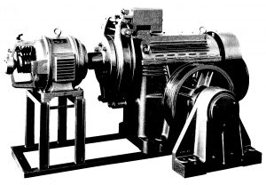
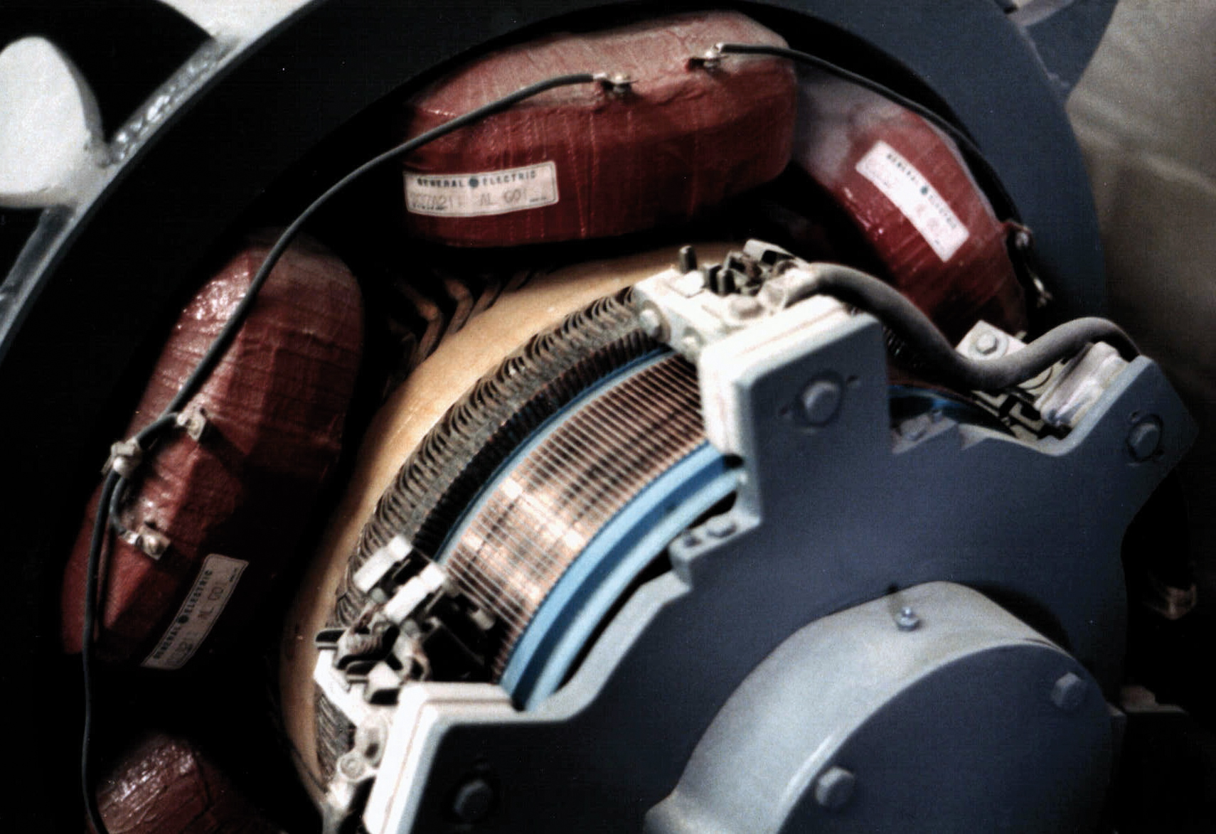
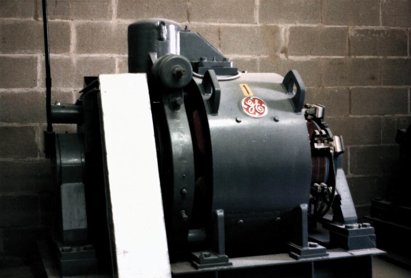
Figure 1 – MB100 machine with slip-ring rotor
Cage asynchronous engines with double winding
In order to make more comfortable the system travel, to ease the “impact” on arrival, and increase the accuracy of stop at landing, since the 50s double pole stator motors were used (4/16, 6/24, 4/24 poles) and Dahlander 4/8 pole motors. The low polarity winding is used for starting and running, the high polarity is inserted at a certain distance from the floor, with consequent reduction of the speed when approaching the stop, making it more comfortable to the stop at landing. These engines made it possible to build lifts with direct starting up to a maximum speed of 0.81 m/s. For higher speeds (up to a maximum of 1.21.5 m/s), to make tolerable the ride comfort, stator resistances were inserted, both at starting at low polarity winding and when slowing at high polarity winding. These resistors should be excluded once the phases of acceleration and deceleration by appropriate timers are terminated, which complicated the control panel operation with a large heat dissipation, especially in systems with a high number of stops and/or travels, with a variation of torque and stopping due to the heat changing the stator resistance.
Engines with external rotors
Among the many types of motors used in the lift (B3, B5, etc., with rotor on bearings or bushings, etc.) the external rotor motors deserve to be mentioned apart. These were quite successful for the cheap cost of their application. The electrical features of these motors were the same as conventional engines, but, from the mechanical point of view, they had the inner stator winding, with the outer rotating part, which at the same time served as a rotor, brake drum and flywheel mass, in order to limit acceleration and braking. They were built with one- or two-polarity winding, as the traditional engines, but, in applications in systems with one polarity and high operating intermittence, as the rotor/braking drum got warmer, lining/drum friction changed, so this greatly changed the levelling of stopping at a landing. With the current regulations, this landing/car difference in height is not tolerable and geared motors still in operation have the motor adjusted by VVVF (Variable Voltage Variable Frequency) to stay within the stopping level established by the standards.
Hydraulic lift motors
A separate consideration concerns cage motors (two-pole) used in the pumps of hydraulic systems. In these systems, the engine starts empty and the torque required at starting is extremely limited. The first hydraulic systems (60s) had an external pump, the engine was industrial type, with high starting currents (810 times the nominal current), low flows and high operating noise, which in some applications was not tolerable. In order to simplify the construction of the unit and reduce the noise, the motor pump was inserted in the unit, permanently submersed in oil. The side effect however is the decrease of the efficiency of the motor because the rotor (at about 2800 g/m) encounters greater resistance when it rotates in the oil than in the air. The high starting current of these engines, combined with an increased power required by the hydraulic systems than comparable cable systems, forced to install even in hydraulic pumps high impedance rotor motors, similar to the engines used in traditional systems rope. Currently, the motors used have limited starting currents (3.5 ÷ 6 times the nominal current, when in oil) and when installed outside the power unit, with pump inside and VVVF speed regulation, they may have excellent efficiency and limited power.
SPEED-CONTROLLED MOTORS
When the lift speed exceeds 1 m/s (for a great ride comfort at arrival and starting with good stopping accuracy and any operating intermittence and load condition), speed controlled motors are preferable so that both at starting and arrival the brake opens and closes with stopped motor, gradual (or variable when needed) acceleration and deceleration.
Direct current motors
Until early 70s, the only speed controlled motor was the DC motor. Lifts used the expensive Ward-Leonard system (asynchronous motor connected to the power supply, mechanically coupled to a dynamo supplying DC to the motor connected to the winch or gearless motor). The speed control was achieved by varying the dynamo voltage.The first controllers provided for the variation via resistors which progressively varied the voltage armature of the d.c. motor, causing the consequent and proportional speed control.This system, conceptually simple but with a very complex and expensive application, offered an excellent ride comfort even at high speed. All systems with long travels and high speeds (up to 4 – 5 m/s) included this type of control. From mid-50s, the resistance regulation was gradually replaced by controllers with magnetic amplifiers and later by electronic amplifiers, keeping the Ward-Leonard system. From mid-70s, the 12 SCR static power converters provided for the direct control of the motor speed by replacing the expensive and noisy motor-dynamo group.These controllers, suppling the d.c. motors with DC voltage rich in harmonics, made the old motors used for the Ward-Leonard system extremely noisy. In order to reduce the noise, various expedients were used, but the results obtained were not optimal. In order to solve the issue, lamellar engines different from classic DC motors were manufactured, specially designed to be powered by electronic controllers.The results were excellent for geared and gearless motors. Even for gearless dc motors, solutions with external rotor were provided.
ACVV cage asynchronous motors
At the same time of the advent of the electronic controllers for DC motors, ACVV (Alternating Current Variable Voltage) controllers for cage asynchronous motors for lifts were designed, both at one speed (four or six poles) and two-speed (generally 4/16 poles). This type of controller provided for a variable supply voltage rich in harmonics, the speed control was achieved by working on the sliding of the rotor, while the braking energy of the system was being dissipated in the rotor. As a result, a normal asynchronous motor for lift became noisy and got warmer. In high speeds and/or high load systems, heavy traffic, etc., the engine suffered from heat waves causing, in some cases, the “uncaging” of the rotor, that is the breaking of the rotor cage bars. In order to overcome these drawbacks, traditional engines described above underwent some changes with increased bodies, rotors with special copper cages, several winding insulation systems, more sophisticated cooling systems, etc. Conceptually these were the same non-controlled engines for lifts, but with significant structural features in the stator and in the rotor.
This type of controller was used only in geared systems, the maximum speed was 1.62 m/s, the maximum load 1,2001,600 kg. In the 80s, these engines in their specific field of application, replaced the DC motors on the market, despite these latter were the best performing and required lower consumptions.
VVVF cage asynchronous motors
In the early 90s, the ACVV regulators were progressively replaced by the more sophisticated VVVF (Variable Voltage Variable Frequency). The high rotor impedance lift motor is particularly ill-suited for this type of controller, it is used only in modernizations where the old motor is kept. The manufacturers of lift motors had to split the production in non-controlled motors and motors for inverters. Inverter motors differ from others for some essential features such as low creep, limited heating, need for reinforced insulation, etc.
The electrical features of the motor are very similar to the first cage motors used in lifts. There are motors dated 50 or 60 years ago controlled by inverters and offering optimal performance very similar to modern engines. VVVF controllers however cause an accelerated aging of the insulation of the motor phases because of voltage peaks.
It is not uncommon to find engines with 40 or 50 years of operation with direct starting, which, after a few months of operation with inverter have a loss of insulation and need to be replaced or rewind, if appropriate protections are not inserted in advance.
In order to overcome this inconvenience, new engines are built with increased insulation windings, both between phases and between phases and earth, but in some cases losses of insulation of the motor have occurred after a limited number of travels.
VVVF controllers are capable of driving asynchronous geared and gearless motors, without any limitation of speed.
With appropriate variants, these are able to recover from the network the braking power of the system with considerable energy savings in systems with long travels and/or speed and loads.
Permanent magnet synchronous motors
Since the beginning of the century many new installations, even with speeds lower than 1 m/s require the use of gearless synchronous motors with permanent magnets (MSMP). These require the use of rare-earth permanent magnets (usually neodymium-iron-boron), they have a more complex structure, can have either internal or external rotor, but, being equal the dimensions, they guarantee higher torques allowing installation in the shaft, thus eliminating the machine room which is hated by designers, expensive for the building constructors, but highly appreciated by maintenance operators. These engines are more expensive than asynchronous motors, the control is more complex, but their features are such that they are preferred to classic asynchronous motors by most manufacturers. The control of permanent magnet motors is different from asynchronous motors, more complex and more expensive.
With these engines there are not speed limitations, they are used in lifting platforms at 0.15 m/s, and in very high speed systems at 15 m/s.
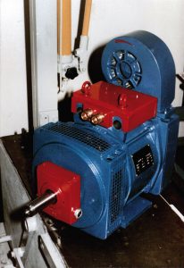
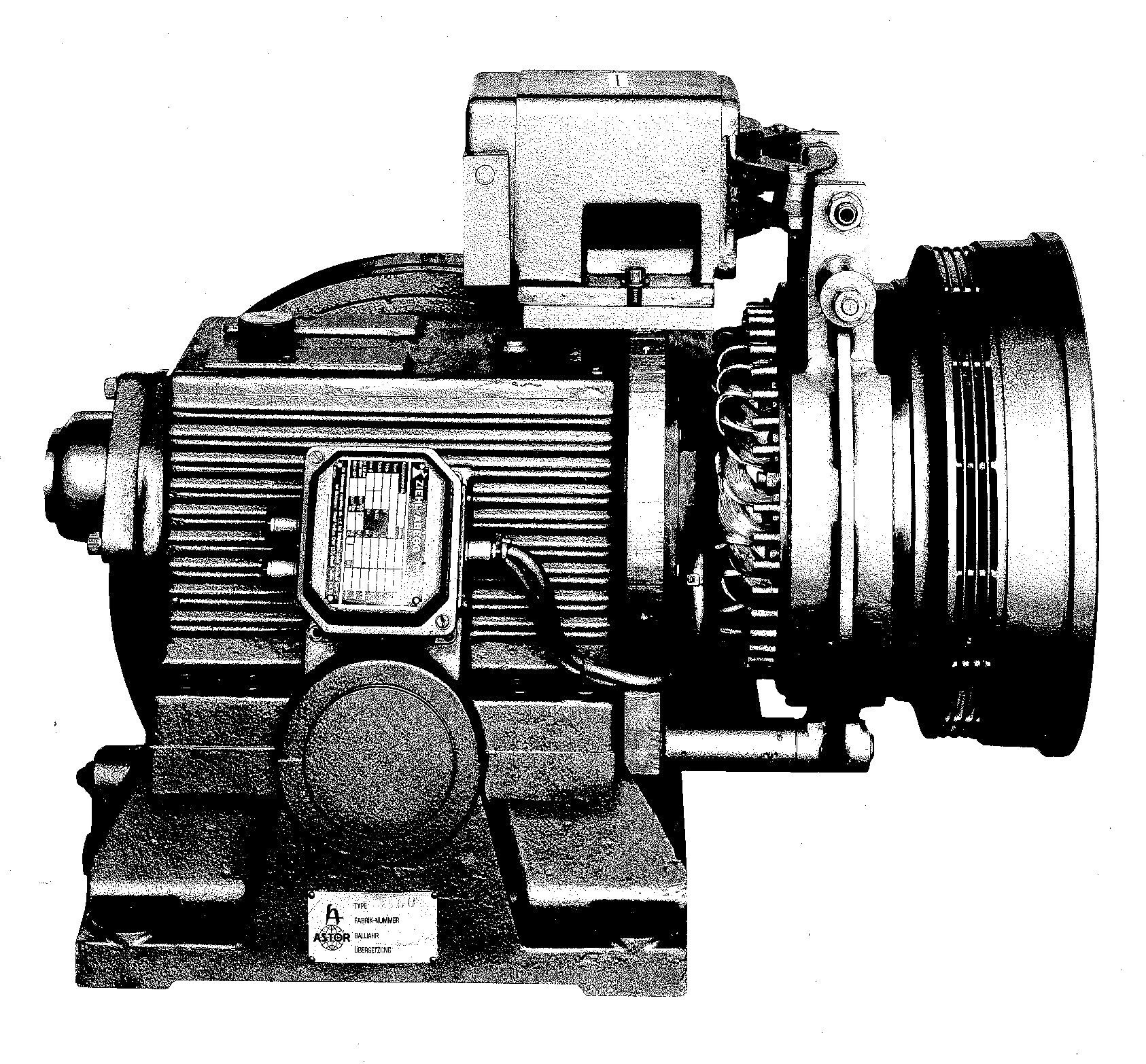
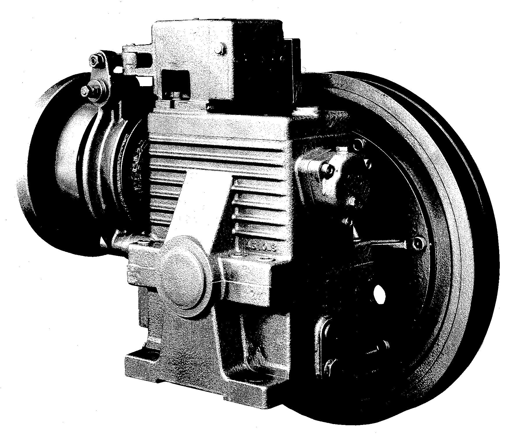
Figure 6 – B3 Sassi motor (1980s)
CONCLUSIONS
We know nothing about the future. We know for sure that in any technical application, both in industry and in civil field, there is always a special attention towards energy saving. We think that what happened in the 80s, when DC motors were abandoned (during the braking phase they recovered the energy from the network, and the advent of ACVV asynchronous motors with energy consumption at braking) will not happen any more. Every new concept will be supported only if it decreases energy consumption.
BIOGRAPHICAL DETAILS
Vittorio Mazzoni, graduated in engineering at the University of Bologna. He worked at Ceam Ascensori from 1973 to 1988 and from 1988 to present at the SMS – Sistemi e Microsistemi (Sassi Holding) of which he is the president.
Bruno Santarelli, is a technical expert in industrial electronics. He worked at Fiam Ascensori from 1969 to 1983; and from 1983 to 2012 at IGV Group.
BIBLIOGRAPHY
Here below a list of articles written by Vittorio Mazzoni, from 2000 until today, for Elevatori magazine.
- Elevatori n.6-2001, page 96: How it works, The differential switch: get to know it – V. Mazzoni
- Elevatori n.5-2004, page 84: Landing floor stop accuracy – V. Mazzoni
- Elevatori n.4-2005, page 66: Education & Training, Modernisation: safety and saving – V. Mazzoni & Ing. L. Calvi
- Elevatori n.1-2007, page 46: Calculations, consumptions and energy saving in lifts – V. Mazzoni
- Elevatori n.4-2010, page 50: The lift energy consumption – V. Mazzoni
- Elevatori n.4-2011, page 52: The lift: power, consumption, energy… – V. Mazzoni
- Elevatori n.6-2011, page 78: How it works, Drives and inverters – Chapter 8 – V. Mazzoni
- Elevatori n.6-2013, page 74: Hydraulic lifts: how to save on bill costs – V. Mazzoni, F. Trabacchi, A. Pini
- Elevatori n.6-2014, page 74: New starting systems for motors in hydraulic lifting installations – V. Mazzoni
By Vittorio Mazzoni(1) & Bruno Santarelli(2)
1 – SMS Sistemi e Microsistemi, Bologna, Italy
2 – IGV Group, Milano, Italy


