Rope/sheave contact wear: a fine tuning – First part
By Nicola Imbimbo –Read the author’s biography
Article appeared for the first time on Elevatori, n. 3/2009. Buy it here.
Rope/sheave contact wear: a fine tuning
ABSTRACT
Steel wire ropes and traction/deflection sheaves are generally considered a “commodity”. This is in a way correct, considering that steel ropes have been produced for over 175 years, but from another point of view there are several aspects that need to be carefully considered. In the beginning of the lift industry, great care was devoted to the checking of specific pressure between ropes and sheaves [5], and also to the linearity of the reeving arrangement.
Not only was this, but also the number of start per hour and rope speed were taken into consideration to assess the maximum value of the specific pressure. It seems that in the recent years such requirement has been withdrawn as it is perceived as “old fashioned”, and the new harmonized standard removed completely any explicit reference to the Specific Pressure calculation.
With the result that today very hard working condition are in service for both ropes and sheaves and consequently shorter life time have to be expected from them.
The aim of this paper is simply to analyze the working condition between ropes and sheaves and pointing out the importance of some issues like specific pressure, deflection angles, sheaves rotated by 90°, etc.
1 – Introduction
Defining the reasons behind the rope/sheave contact wear is not a simple issue: a lot of parameters interact with each other and further to this their mutual relationship are not always clearly understood.
Despite that some simplification could be addressed just to identify the mean causes of “fast” wear when this happens in service after a short period of time. On a traction lift the car movement is achieved by the combination of a finely tuned system; the rope/sheave.
These two elements are transmitting with each other movement with surface contact that in turn creates friction. The surface interaction that develops wear is the main point that will be analyzed hereafter.
Depending on the condition of this contact a lot of consequences are generated into the daily working activity of the traction lift.
Due to the fact that no technical rules are available to address surface wear, and that little extensive research has been performed related to this topic, the following information reported are mainly based on experience gained on the application field. The numerical values reported in this paper are intended only as a rough reference and are purely indicative. All the examples are based on ropes and sheaves manufactured to current standards that technology allows.
2 – Assessment of the main causes affecting Rope/Sheave wear
There are a lot of elements contributing to each other affecting the performance of the rope/sheave wear in service. In the following an attempt is mode to identify the main elements involved in this relationship to understand the different influences that they could develop and in which way they could influence each other.
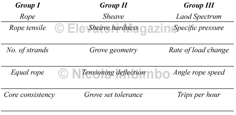
Before starting the analysis of main elements, it is important to subdivide them into groups, just to have a rough identification.
Causes affecting the surface wear can be classified into the three main groups of elements:
1. rope
2. sheave
3. load spectrum.
Table 1 – Classification of main causes of surface wear

The above table makes no presumption to be exhaustive. It only deals with the main elements affecting the performance in service of the contact Rope/Sheave.
The way in which the several parameters affect each other is not a simple issue to be assessed, and to try and illustrate this in the table have been drawn three coloured arrows to represent the transversal relationship between the elements:
– Red arrow → raw material relationship
– Black arrow → fine tuning relationship
– Blue arrow → design relationship.
Several other relations could have been identified, but for simple and clear understanding only the above mentioned have been drawn on the table.
This simple classification of the main elements will help in the following description to understand the phenomena that will be discussed, keeping clearly in mind that the wear appearance of the sheaves could have different forms: surface wear or negative imprinting or even a combination of the two.
Such imprints shapes are the result of a combination of several causes that have to be present at the same time to create the above mentioned phenomena.
One of the causes mentioned in Table 1 is not enough to create surface wear, but a combination of few of them could easily lead to the expected wear very quickly. This will be clarified in the following paragraphs.
3 – DEFINITION OF THE CONTACT: STATIC POINT OF VIEW
3.1 Number of strands
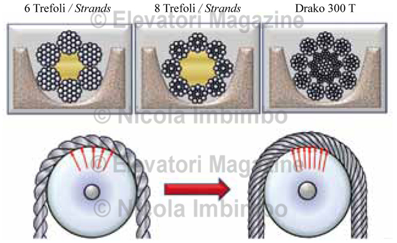
Before discussing the details of the various elements that are affecting the wear of both rope and sheaves, we must understand how this contact varies in the groove depending on the number of strands in the rope and this can range from 6 strands up to 9 strands. The most commonly used ropes are the fibre cored with 6 or 8 strands, but a lot more constructions are available in the market: full steel core, mixed core (fibre and metallic), natural fibre core and man-made fibre core (synthetic cores). The most simple indication on the number of points of contact is to look at the cross section of the rope and to examine how
many strands are in contact with the shape of the groove (see the upper part of the Figure 1); but this is not the only element to be considered.
Of greater importance is to examine the longitudinal contact between ropes and sheave (see the bottom part of Figure 1), because a rope with a higher number of outer strands, produces in turn a higher number of points of contact.
In practical terms this means that in a stated condition, if a rope with a higher number of strands is selected, the surface of contact is increased and also the actual local pressure contact is reduced [8,12].

Figure 1 – Increased number of points of contact with the sheave having rope with more outer strands.
3.2 Elementary wires contact

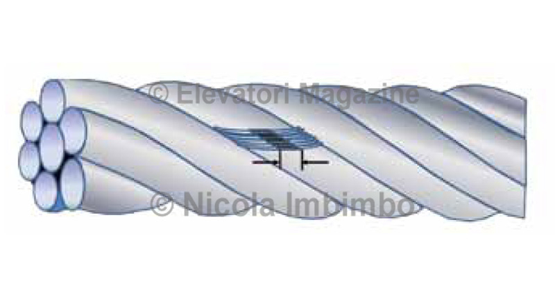
Figure 2 – Basic element of surface contact between a sheave and a rope of 6 strands ordinary lay
When two steel surfaces come into contact, especially when they have different shapes and thus the surface contact will be on discrete points, the first elements that will drive their relationship will be the reciprocal hardness [8] in conjunction with the contact pressure: from a static point of view when the two surfaces contact each other with great pressure, the hardest one tends to generate elastic-plastic deformation of the softest one.
In the particular case of contact between rope and sheave, it must be understood that the harder surface is the wire and to this must also be added that the contact surface is limited to a discrete “collection” of parallel wires, as represented in the Figure 2.
